How to Create a New Project in Autodesk Electrical
Creating a new project in Autodesk Electrical involves several detailed steps to ensure that your project is set up correctly, efficiently, and ready for electrical design tasks. This comprehensive guide will walk you through the entire process, from initial setup to final project organization. By following these steps, you can ensure that your projects are well-organized and optimized for successful electrical design.
1. Preparing for a New Project
Before starting a new project, it’s important to prepare your environment and gather all necessary information and resources.
Gather Project Information
- Project Scope: Define the scope of your project. Understand what you need to accomplish, including the type of electrical systems you’ll be designing.
- Project Requirements: Gather all necessary requirements and specifications. This includes electrical standards, component lists, and any client-specific requirements.
- Resource Availability: Ensure that you have all required resources, including component libraries, templates, and reference materials.
Create a Project Folder
- Organize Your Files: Create a dedicated folder on your computer or network drive where all project-related files will be stored. This helps keep your project organized and accessible.
2. Launching Autodesk Electrical
- Open Autodesk Electrical: Start by launching Autodesk Electrical from your desktop or start menu.
- Welcome Screen: Upon launching, you will be greeted with the welcome screen. From here, you can create a new project, open an existing project, or access recent files.
3. Creating a New Project
To create a new project, follow these detailed steps:
Access the Project Manager
- Open Project Manager: From the welcome screen or main toolbar, click on the ‘Project Manager’ icon. This will open the Project Manager window, which is your main interface for managing projects in Autodesk Electrical.
Create a New Project
- New Project Button: In the Project Manager window, click on the ‘New Project’ button.
- Project Name and Location: A dialog box will appear prompting you to enter a project name and specify the location where the project files will be saved. Enter a descriptive name for your project and choose the project folder you created earlier.
- Project Template: If you have a project template, select it from the list. Templates can save time by pre-configuring settings and including standard components and drawings.
Project Details
- Project Description: Enter a brief description of the project. This helps in identifying the project and understanding its purpose at a glance.
- Project Number: Assign a unique project number if required. This is useful for tracking and reference purposes.
4. Configuring Project Settings
Once the new project is created, you need to configure its settings to match your design requirements.
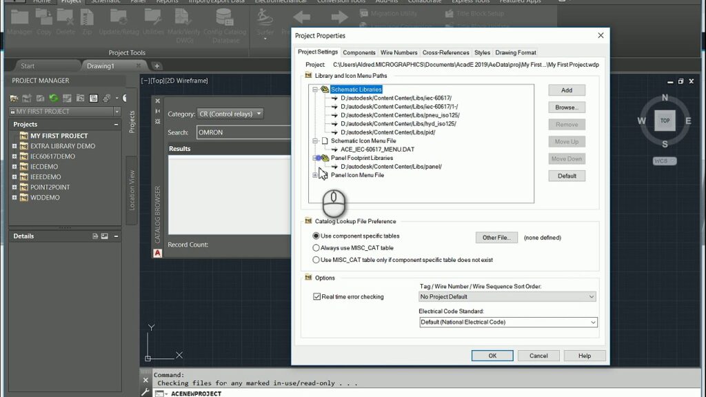
Project Properties
- Open Project Properties: In the Project Manager window, right-click on your newly created project and select ‘Properties’ from the context menu.
- General Settings: The General tab includes basic project information such as name, description, and number. Ensure these details are correct.
- Drawing Format: Specify the default drawing format for new drawings in the project. This includes settings such as sheet size, title block, and border.
Electrical Standards
- Standards Tab: Navigate to the ‘Standards’ tab to configure electrical standards for the project.
- Default Standards: Set the default electrical standards, such as IEC, ANSI, JIS, etc. This ensures that all components and designs adhere to the specified standard.
- Wire Numbers: Configure wire numbering settings, including format, start number, and increment.
- Cross-Referencing: Set up cross-referencing preferences for components and wires. This helps in maintaining clear and consistent references across the project.
Drawing Properties
- Default Layers: In the ‘Drawing Properties’ tab, configure default layers for different types of electrical elements, such as wires, components, and text. This helps in maintaining an organized and readable schematic.
- Annotation Settings: Set default annotation settings, including text style, size, and color. Consistent annotations improve the clarity of your drawings.
BOM and Reports
- BOM Settings: Configure Bill of Materials (BOM) settings under the ‘Reports’ tab. Specify the fields to include in the BOM and their format.
- Report Templates: Select or create templates for different types of reports you will generate during the project. This ensures consistency and completeness in project documentation.
5. Creating Project Drawings
With your project settings configured, you can now start creating the electrical drawings for your project.
Create a New Drawing
- New Drawing Button: In the Project Manager window, right-click on the project name and select ‘New Drawing’ from the context menu.
- Drawing Name: Enter a name for the new drawing and specify its location within the project folder.
- Drawing Template: If you have a drawing template, select it to use predefined settings and layouts.
Drawing Settings
- Drawing Properties: Before starting the design, configure the drawing properties to match the project settings. Right-click on the drawing name in the Project Manager and select ‘Properties’.
- Title Block and Border: Ensure the title block and border match the project’s drawing format.
6. Inserting Components and Symbols
With the drawing ready, you can start inserting electrical components and symbols.
Component Libraries
- Access Libraries: From the main toolbar, click on the ‘Insert Component’ button to access the component libraries.
- Select Library: Choose the appropriate library based on the project’s electrical standard.
- Search and Select Components: Use the search function to find specific components or browse through the library to select components.
Insert Components
- Place Component: Click on the desired component and place it on the drawing. Adjust its position using the mouse.
- Component Properties: After placing the component, a properties dialog box will appear. Enter the necessary details, such as component tag, description, and catalog number.
Connect Components with Wires
- Draw Wires: Select the ‘Wire’ tool from the toolbar. Click to start drawing a wire from one component to another.
- Wire Properties: Configure wire properties, such as color, layer, and type, to match project standards.
- Wire Numbers: If automatic wire numbering is enabled, the wires will be numbered based on the project’s wire numbering settings.
7. Adding Annotations and Labels
Annotations and labels are crucial for clear and understandable electrical schematics.
Insert Text Annotations
- Text Tool: Select the ‘Text’ tool from the toolbar.
- Place Text: Click on the drawing to place the text annotation. Enter the text in the dialog box and configure its properties, such as font, size, and color.
Label Components and Wires
- Component Labels: Use the ‘Insert Component Label’ tool to add labels to components. Configure the label properties to include necessary information like component tag and description.
- Wire Labels: Similarly, use the ‘Insert Wire Label’ tool to label wires with their respective wire numbers and other relevant information.
8. Creating and Using Circuits
Circuits are groups of components and wires that function together. Creating and using circuits efficiently can save time and ensure consistency.
Create a Circuit
- Circuit Builder Tool: Access the ‘Circuit Builder’ tool from the main toolbar.
- Select Components: Choose the components to include in the circuit. Configure their properties as needed.
- Save Circuit: Once the circuit is configured, save it to the project library for future use.
Insert a Circuit
- Insert Saved Circuit: Use the ‘Insert Circuit’ tool to place a saved circuit into a drawing. This reduces repetitive work and ensures consistency.
- Adjust Connections: After inserting the circuit, adjust the connections and properties as needed to fit the specific context of your drawing.
9. Managing and Organizing Drawings
Effective management and organization of your drawings ensure smooth project progression and easier modifications.
Organize Drawings in Folders
- Create Folders: In the Project Manager, right-click on the project name and select ‘New Folder’. Name the folder appropriately based on its contents.
- Move Drawings: Drag and drop drawings into the appropriate folders to keep related drawings together.
Cross-Referencing
- Automatic Cross-Referencing: Enable automatic cross-referencing in the project settings to maintain links between related components and wires across different drawings.
- Manual Cross-Referencing: Use the ‘Insert Cross-Reference’ tool to manually create cross-references where needed.
10. Generating Reports
Reports provide a detailed overview of various aspects of your project, such as the Bill of Materials, wire lists, and component summaries.
Generate BOM
- Access Reports Tool: From the main toolbar, click on the ‘Reports’ tool.
- Select Report Type: Choose ‘Bill of Materials’ from the list of available reports.
- Configure Report: Configure the report settings, including fields to include, sorting order, and format.
- Generate and Save Report: Click ‘Generate’ to create the report. Save it in the project folder for documentation.
Other Reports
- Wire List: Generate a wire list report to get a detailed overview of all wires used in the project, including their properties and connections.
- Component Summary: Generate a component summary report to list all components used in the project, including their tags, descriptions, and catalog numbers.
11. Collaborating with Team Members
Collaboration is key to successful project completion, especially in larger teams.
Sharing Project Files
- Network Drive: Save the project folder on a shared network drive accessible to all team members.
- Cloud Storage: Use cloud storage services like Autodesk Drive or other third-party services to share project files.
Version Control
- Versioning System: Implement a versioning system to track changes and maintain a history of project files.
- File Naming Conventions: Use consistent file naming conventions to avoid confusion and ensure that everyone is working on the correct version.
12. Reviewing and Finalizing the Project
Before finalizing the project, a thorough review is essential to catch any errors or omissions.
Project Review
- Cross-Check Components: Verify that all components are correctly placed and labeled.
- Verify Connections: Ensure all connections are correctly made and labeled.
Final Adjustments
- Adjust Drawings: Make any necessary adjustments to the drawings based on the review.
- Update Reports: Regenerate reports to reflect any changes made during the review.
Project Documentation
- Compile Documentation: Compile all project documentation, including drawings, reports, and specifications.
- Final Backup: Create a final backup of the project folder for safekeeping and future reference.
Conclusion
Creating a new project in Autodesk Electrical involves a series of well-defined steps, from initial setup to final project organization. By following this comprehensive guide, you can ensure that your projects are set up correctly, efficiently, and are well-documented. This not only enhances the quality of your electrical designs but also streamlines the workflow, making it easier to manage and collaborate on projects.
Regularly updating your skills and staying informed about new features and best practices in Autodesk Electrical will further improve your efficiency and project outcomes. Happy designing!