How to Integrate AutoCAD Electrical with Autodesk Inventor
Integration between AutoCAD Electrical and Autodesk Inventor allows for seamless collaboration between electrical and mechanical design teams. This synergy ensures that electrical schematics and mechanical models are aligned, reducing errors and streamlining the design process. This comprehensive guide will cover the various aspects of integrating AutoCAD Electrical with Autodesk Inventor, including setup, workflows, and best practices.
Table of Contents
- Introduction
- 1.1 Overview of AutoCAD Electrical and Autodesk Inventor
- 1.2 Benefits of Integration
- 1.3 Prerequisites
- Setting Up the Integration Environment
- 2.1 Software Installation and Licensing
- 2.2 Configuring AutoCAD Electrical for Integration
- 2.3 Configuring Autodesk Inventor for Integration
- Data Exchange Methods
- 3.1 DWG Format Exchange
- 3.2 IDF and XML File Formats
- 3.3 Using the Electromechanical Link
- Working with Electromechanical Projects
- 4.1 Creating and Managing Projects
- 4.2 Linking Electrical and Mechanical Components
- 4.3 Synchronizing Data Between AutoCAD Electrical and Inventor
- Component and Symbol Libraries
- 5.1 Standardizing Libraries Across Platforms
- 5.2 Creating Custom Libraries
- 5.3 Sharing and Updating Libraries
- Wire and Cable Management
- 6.1 Creating Wire and Cable Schematics in AutoCAD Electrical
- 6.2 Routing Wires and Cables in Inventor
- 6.3 Synchronizing Wire and Cable Data
- Generating Reports and Documentation
- 7.1 Bill of Materials (BOM)
- 7.2 Wiring and Cable Reports
- 7.3 Customizing Report Formats
- Advanced Integration Techniques
- 8.1 Using API for Custom Integration
- 8.2 Automating Workflows with Scripts
- 8.3 Integrating with PLM Systems
- Troubleshooting and Support
- 9.1 Common Issues and Solutions
- 9.2 Resources for Help and Support
- 9.3 Best Practices for Maintenance
- Case Studies and Real-World Applications
- 10.1 Industry Examples
- 10.2 Lessons Learned from Implementations
- 10.3 Future Trends in Electromechanical Integration
1. Introduction
1.1 Overview of AutoCAD Electrical and Autodesk Inventor
AutoCAD Electrical is a specialized version of AutoCAD, designed specifically for electrical control system designers. It offers comprehensive tools for creating electrical schematics, panel layouts, and other related documentation.
Autodesk Inventor is a powerful 3D CAD software for mechanical design, simulation, visualization, and documentation. It enables engineers to create detailed 3D models and assemblies, perform simulations, and generate accurate technical drawings.
1.2 Benefits of Integration
Integrating AutoCAD Electrical with Autodesk Inventor offers numerous benefits:
- Enhanced Collaboration: Facilitates better communication and coordination between electrical and mechanical design teams.
- Reduced Errors: Ensures consistency between electrical schematics and mechanical models, reducing the risk of design errors.
- Streamlined Workflows: Automates data exchange and synchronization, improving efficiency and productivity.
- Comprehensive Documentation: Generates unified reports and documentation, encompassing both electrical and mechanical aspects of the design.
1.3 Prerequisites
Before starting the integration process, ensure you have the following:
- Licensed versions of AutoCAD Electrical and Autodesk Inventor.
- Basic knowledge of using both software applications.
- Administrative rights to install and configure software.
- A clear understanding of the project requirements and workflows.
2. Setting Up the Integration Environment
2.1 Software Installation and Licensing
Ensure that both AutoCAD Electrical and Autodesk Inventor are installed and properly licensed on your system. Follow the installation guides provided by Autodesk to complete the installation process.
2.2 Configuring AutoCAD Electrical for Integration
- Launch AutoCAD Electrical: Open AutoCAD Electrical and navigate to the Options menu.
- Set File Paths: Configure the file paths for projects, libraries, and support files to ensure consistent data access.
- Enable Electromechanical Link: In the project settings, enable the electromechanical link feature to allow communication between AutoCAD Electrical and Inventor.
2.3 Configuring Autodesk Inventor for Integration
- Launch Autodesk Inventor: Open Autodesk Inventor and access the Application Options.
- Set File Locations: Configure the file locations for projects, libraries, and templates.
- Enable Electromechanical Link: In the electromechanical tab, enable the integration with AutoCAD Electrical.
3. Data Exchange Methods
3.1 DWG Format Exchange
The DWG file format is the native file format for AutoCAD-based applications. It can be used to exchange data between AutoCAD Electrical and Autodesk Inventor.
Steps:
- Exporting DWG from AutoCAD Electrical:
- Use the Export function to save the electrical schematics as a DWG file.
- Ensure all relevant layers and objects are included in the export.
- Importing DWG into Inventor:
- Open Autodesk Inventor and use the Import function to load the DWG file.
- Map the DWG layers to appropriate Inventor layers.
3.2 IDF and XML File Formats
IDF (Intermediate Data Format) and XML (Extensible Markup Language) are commonly used file formats for data exchange between electrical and mechanical CAD applications.
Steps:
- Exporting IDF/XML from AutoCAD Electrical:
- Use the Export function to save the electrical data as an IDF or XML file.
- Ensure all necessary components and connections are included.
- Importing IDF/XML into Inventor:
- Use the Import function in Inventor to load the IDF or XML file.
- Verify the imported data and make necessary adjustments.
3.3 Using the Electromechanical Link
The Electromechanical Link feature provides a direct connection between AutoCAD Electrical and Autodesk Inventor, enabling real-time data synchronization.
Steps:
- Enable Electromechanical Link in AutoCAD Electrical:
- In the project settings, enable the Electromechanical Link feature.
- Enable Electromechanical Link in Inventor:
- In the electromechanical tab, enable the integration with AutoCAD Electrical.
- Link Components:
- Link electrical components in AutoCAD Electrical with their corresponding mechanical counterparts in Inventor.
- Synchronize Data:
- Use the synchronization tools to update data between the two applications, ensuring consistency.
4. Working with Electromechanical Projects
4.1 Creating and Managing Projects
Creating and managing electromechanical projects involves setting up projects in both AutoCAD Electrical and Autodesk Inventor and linking them for seamless data exchange.
Steps:
- Create Project in AutoCAD Electrical:
- Open AutoCAD Electrical and create a new project.
- Define the project settings and configure the file paths.
- Create Project in Inventor:
- Open Autodesk Inventor and create a new project.
- Define the project settings and configure the file paths.
- Link Projects:
- Use the Electromechanical Link feature to link the projects in AutoCAD Electrical and Inventor.
- Ensure that the project settings and file paths are correctly configured for synchronization.
4.2 Linking Electrical and Mechanical Components
Linking electrical and mechanical components ensures that the designs in AutoCAD Electrical and Inventor are synchronized.
Steps:
- Identify Components:
- Identify the electrical components in AutoCAD Electrical that need to be linked with mechanical components in Inventor.
- Link Components:
- Use the linking tools in both applications to establish connections between corresponding components.
- Verify Links:
- Verify that the components are correctly linked and that data is synchronized.
4.3 Synchronizing Data Between AutoCAD Electrical and Inventor
Data synchronization ensures that changes made in one application are reflected in the other.
Steps:
- Initiate Synchronization:
- Use the synchronization tools in AutoCAD Electrical and Inventor to start the synchronization process.
- Resolve Conflicts:
- Resolve any conflicts that arise during synchronization, such as component mismatches or data inconsistencies.
- Verify Data:
- Verify that the data in both applications is up-to-date and consistent.
5. Component and Symbol Libraries
5.1 Standardizing Libraries Across Platforms
Standardizing libraries ensures consistency between AutoCAD Electrical and Inventor, making it easier to manage components and symbols.
Steps:
- Create Standard Libraries:
- Create standardized libraries for components and symbols that can be used in both applications.
- Distribute Libraries:
- Distribute the libraries to all team members and ensure they are used consistently.
- Update Libraries:
- Regularly update the libraries to include new components and symbols.
5.2 Creating Custom Libraries
Custom libraries can be created to meet specific project requirements.
Steps:
- Identify Requirements:
- Identify the specific requirements for custom components and symbols.
- Create Custom Components:
- Use the tools in AutoCAD Electrical and Inventor to create custom components and symbols.
- Add to Libraries:
- Add the custom components and symbols to the libraries for use in future projects.
5.3 Sharing and Updating Libraries
Sharing and updating libraries ensures that all team members have access to the latest components and symbols.
Steps:
- Share Libraries:
- Use a shared network location or cloud storage to share libraries with team members.
- Update Libraries:
- Regularly update the libraries and notify team members of changes.
- Verify Consistency:
- Verify that all team members are using the latest libraries and that there are no discrepancies.
6. Wire and Cable Management
6.1 Creating Wire and Cable Schematics in AutoCAD Electrical
Creating wire and cable schematics involves defining the wiring and cable connections in AutoCAD Electrical.
Steps:
- Create Schematic:
- Use the tools in AutoCAD Electrical to create the wire and cable schematic.
- Define Connections:
- Define the connections between components, including wire and cable types, lengths, and labels.
- Verify Schematic:
- Verify the schematic to ensure that all connections are correctly defined and that there are no errors.
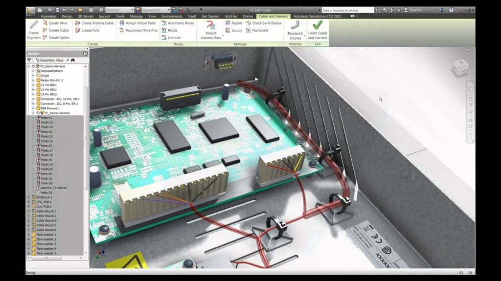
6.2 Routing Wires and Cables in Inventor
Routing wires and cables in Inventor involves defining the physical paths for wires and cables in the 3D model.
Steps:
- Import Schematic:
- Import the wire and cable schematic from AutoCAD Electrical into Inventor.
- Define Routes:
- Use the routing tools in Inventor to define the physical paths for wires and cables.
- Verify Routes:
- Verify that the routes are correctly defined and that there are no conflicts or errors.
6.3 Synchronizing Wire and Cable Data
Synchronizing wire and cable data ensures consistency between the schematic in AutoCAD Electrical and the 3D model in Inventor.
Steps:
- Initiate Synchronization:
- Use the synchronization tools in AutoCAD Electrical and Inventor to start the synchronization process.
- Resolve Conflicts:
- Resolve any conflicts that arise during synchronization, such as mismatched wire and cable data.
- Verify Data:
- Verify that the wire and cable data in both applications is up-to-date and consistent.
7. Generating Reports and Documentation
7.1 Bill of Materials (BOM)
Generating a Bill of Materials (BOM) provides a comprehensive list of all components used in the project.
Steps:
- Generate BOM in AutoCAD Electrical:
- Use the reporting tools in AutoCAD Electrical to generate the BOM.
- Generate BOM in Inventor:
- Use the reporting tools in Inventor to generate the BOM.
- Combine BOMs:
- Combine the BOMs from both applications to create a comprehensive list of components.
7.2 Wiring and Cable Reports
Wiring and cable reports provide detailed information about the wiring and cable connections in the project.
Steps:
- Generate Wiring Report in AutoCAD Electrical:
- Use the reporting tools in AutoCAD Electrical to generate the wiring report.
- Generate Cable Report in Inventor:
- Use the reporting tools in Inventor to generate the cable report.
- Combine Reports:
- Combine the wiring and cable reports to create a comprehensive document.
7.3 Customizing Report Formats
Customizing report formats ensures that the reports meet specific project requirements.
Steps:
- Define Requirements:
- Define the specific requirements for the report formats.
- Customize Reports in AutoCAD Electrical:
- Use the customization tools in AutoCAD Electrical to modify the report formats.
- Customize Reports in Inventor:
- Use the customization tools in Inventor to modify the report formats.
- Verify Reports:
- Verify that the customized reports meet the project requirements.
8. Advanced Integration Techniques
8.1 Using API for Custom Integration
Using the API (Application Programming Interface) allows for custom integration between AutoCAD Electrical and Inventor.
Steps:
- Learn the API:
- Familiarize yourself with the APIs for both AutoCAD Electrical and Inventor.
- Develop Custom Integration:
- Use the APIs to develop custom integration solutions that meet specific project requirements.
- Test Integration:
- Thoroughly test the custom integration to ensure that it works correctly and efficiently.
8.2 Automating Workflows with Scripts
Automating workflows with scripts can improve efficiency and reduce manual effort.
Steps:
- Identify Repetitive Tasks:
- Identify tasks that are repetitive and can be automated.
- Develop Scripts:
- Use scripting languages such as AutoLISP (for AutoCAD Electrical) and VBA (for Inventor) to develop automation scripts.
- Implement Scripts:
- Implement the scripts in the workflow and verify that they work as expected.
8.3 Integrating with PLM Systems
Integrating with PLM (Product Lifecycle Management) systems ensures that the project data is managed and controlled throughout its lifecycle.
Steps:
- Select a PLM System:
- Select a PLM system that supports integration with AutoCAD Electrical and Inventor.
- Configure Integration:
- Configure the integration between the PLM system and the CAD applications.
- Manage Data:
- Use the PLM system to manage and control the project data throughout its lifecycle.
9. Troubleshooting and Support
9.1 Common Issues and Solutions
Issue: Data Synchronization Errors Solution: Verify the electromechanical link settings and ensure that both applications are correctly configured for synchronization.
Issue: Component Linking Errors Solution: Ensure that components are correctly identified and linked between AutoCAD Electrical and Inventor.
Issue: Report Generation Errors Solution: Verify the report settings and ensure that all necessary data is included in the reports.
9.2 Resources for Help and Support
Official Autodesk Support:
- Access the Autodesk Knowledge Network for articles, tutorials, and support resources.
- Contact Autodesk support for assistance with technical issues.
Community Forums:
- Participate in Autodesk community forums to ask questions and share knowledge with other users.
Online Courses:
- Enroll in online courses to learn more about using AutoCAD Electrical and Inventor.
9.3 Best Practices for Maintenance
Regular Updates:
- Regularly update both AutoCAD Electrical and Inventor to the latest versions to ensure compatibility and access to new features.
Backup Data:
- Regularly backup project data to prevent data loss in case of technical issues.
Documentation:
- Maintain thorough documentation of the integration process and any customizations made.
10. Case Studies and Real-World Applications
10.1 Industry Examples
Manufacturing Industry:
- Companies in the manufacturing industry use the integration to design and document complex machinery with both electrical and mechanical components.
Automotive Industry:
- The automotive industry uses the integration to design and simulate electrical systems within vehicles.
Aerospace Industry:
- Aerospace companies use the integration to ensure that electrical and mechanical systems are accurately designed and documented.
10.2 Lessons Learned from Implementations
Effective Communication:
- Ensure effective communication between electrical and mechanical design teams to avoid misunderstandings and errors.
Thorough Testing:
- Thoroughly test the integration to identify and resolve any issues before they impact the project.
Continuous Improvement:
- Continuously improve the integration process based on feedback and lessons learned from previous projects.
10.3 Future Trends in Electromechanical Integration
Increased Automation:
- Future trends indicate increased automation in the integration process, reducing manual effort and improving efficiency.
Enhanced Collaboration Tools:
- Enhanced collaboration tools will facilitate better communication and coordination between design teams.
Integration with IoT:
- Integration with IoT (Internet of Things) will enable real-time monitoring and control of electrical and mechanical systems.
Integrating AutoCAD Electrical with Autodesk Inventor offers significant benefits for designing and documenting electromechanical systems. By following the steps outlined in this guide, you can set up the integration environment, manage projects and components, synchronize data, and generate comprehensive reports. Leveraging advanced techniques such as using APIs and automating workflows can further enhance efficiency and productivity. Regular maintenance, effective troubleshooting, and continuous improvement will ensure successful integration and project outcomes.