How to Use Parametric Drawing in BricsCAD
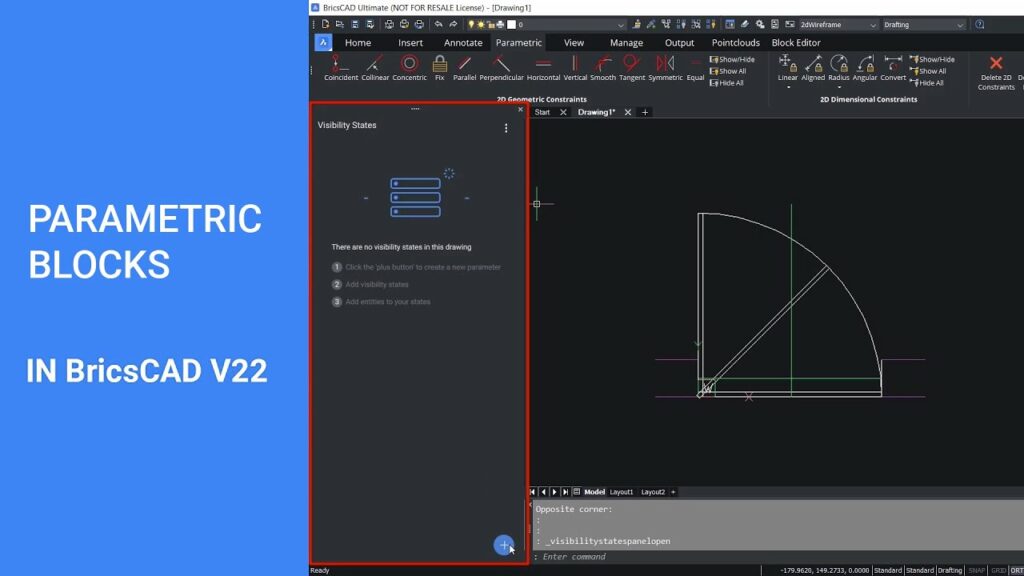
Parametric drawing in BricsCAD is a powerful feature that allows designers to create and modify their designs using parameters and constraints. This methodology ensures that the design can be easily updated, scaled, or adjusted without manually redrawing elements. This comprehensive guide covers the basics and advanced techniques of parametric drawing in BricsCAD, from setup to practical applications.
Table of Contents
- Introduction to Parametric Drawing
- What is Parametric Drawing?
- Benefits of Parametric Drawing
- Setting Up BricsCAD for Parametric Drawing
- Installing BricsCAD
- Configuring the Workspace
- Understanding Parameters and Constraints
- Types of Parameters
- Types of Constraints
- Creating a Parametric Drawing
- Basic Sketching
- Applying Constraints
- Defining Parameters
- Advanced Parametric Drawing Techniques
- Creating Parametric Assemblies
- Using Formulas and Equations
- Parametric 3D Modeling
- Managing Parametric Drawings
- Editing and Updating Parameters
- Using the Parameters Manager
- Linking Parameters Across Drawings
- Practical Applications of Parametric Drawing
- Architectural Design
- Mechanical Design
- Product Design
- Troubleshooting and Optimization
- Common Issues and Solutions
- Performance Optimization
- Best Practices
- Conclusion
1. Introduction to Parametric Drawing
What is Parametric Drawing?
Parametric drawing is a design approach where the geometry and dimensions of the drawing are controlled by parameters and constraints. Parameters can be variables or constants that define the properties of the design, while constraints are rules that dictate the relationships and behavior of different elements in the drawing.
Benefits of Parametric Drawing
- Flexibility: Easily modify designs by changing parameters, without the need for extensive redrawing.
- Accuracy: Maintain precise control over dimensions and relationships between elements.
- Efficiency: Save time by automating repetitive tasks and ensuring consistent updates across the design.
- Scalability: Adapt designs to different requirements and scales by adjusting parameters.
2. Setting Up BricsCAD for Parametric Drawing
Installing BricsCAD
- Download BricsCAD: Visit the BricsCAD website and download the latest version of the software.
- Installation: Follow the installation instructions to install BricsCAD on your computer.
- Activation: Activate your license to access the full features of BricsCAD.
Configuring the Workspace
- Switch to Mechanical or BIM Workspace: BricsCAD offers specialized workspaces for different types of projects. Switch to the Mechanical or BIM workspace for enhanced parametric drawing tools.
- Customize Toolbars and Panels: Arrange toolbars and panels to include parametric drawing tools for easy access.
- Set Preferences: Configure your preferences for units, grid settings, and snapping options to match your design needs.
3. Understanding Parameters and Constraints
Types of Parameters
- Dimensional Parameters: Define the size and position of geometric elements (e.g., lengths, diameters).
- Geometric Parameters: Control the relationships between geometric elements (e.g., angle between lines, distance between points).
- User-defined Parameters: Custom parameters defined by the user to control specific aspects of the design.
Types of Constraints
- Geometric Constraints:
- Coincident: Ensures that two points coincide.
- Parallel: Ensures that two lines are parallel.
- Perpendicular: Ensures that two lines are perpendicular.
- Horizontal/Vertical: Ensures that lines or axes are horizontal or vertical.
- Tangent: Ensures that a line or curve is tangent to another curve.
- Dimensional Constraints:
- Linear: Defines a fixed distance between two points.
- Angular: Defines a fixed angle between two lines.
- Radial: Defines a fixed radius for circles and arcs.
- Diameter: Defines a fixed diameter for circles.
4. Creating a Parametric Drawing
Basic Sketching
- Create a New Drawing: Start a new drawing in BricsCAD.
- Draw Basic Shapes: Use basic drawing tools (line, circle, rectangle) to create the initial sketch.
- Set Up Grid and Snapping: Enable grid and snapping options to ensure precise placement of elements.
Applying Constraints
- Select Elements: Select the elements you want to constrain.
- Apply Geometric Constraints:
- Use the
CONSTRAINTcommand or the Constraints toolbar to apply constraints like parallel, perpendicular, and tangent.
- Use the
- Apply Dimensional Constraints:
- Use the
DIMCONSTRAINTcommand to apply dimensional constraints like linear, angular, and radial.
- Use the
Defining Parameters
- Access Parameters Manager: Open the Parameters Manager from the Constraints toolbar or the Manage tab.
- Define Parameters:
- Create new parameters and assign values.
- Link parameters to dimensional constraints to control the dimensions of elements.
- Use Parameters in Equations:
- Use equations to define relationships between parameters (e.g., Length2 = Length1 * 2).
5. Advanced Parametric Drawing Techniques
Creating Parametric Assemblies
- Create Individual Parts: Create separate drawings for each part of the assembly.
- Define Parameters for Each Part: Apply parameters and constraints to control the dimensions and relationships of each part.
- Assemble Parts:
- Use the
INSERTcommand to place parts in the assembly drawing. - Apply assembly constraints to control the position and orientation of parts.
- Use the
Using Formulas and Equations
- Define Complex Relationships: Use formulas and equations to define complex relationships between parameters (e.g., Pythagorean theorem for diagonal calculations).
- Parameter Linking: Link parameters from different parts or drawings to create a cohesive parametric model.
Parametric 3D Modeling
- Create 3D Sketches: Use 3D drawing tools to create sketches in three dimensions.
- Apply 3D Constraints: Apply 3D geometric and dimensional constraints to control the shape and position of 3D elements.
- Use Parameters in 3D Models: Define parameters to control the dimensions and relationships of 3D features.
6. Managing Parametric Drawings
Editing and Updating Parameters
- Access Parameters Manager: Open the Parameters Manager to view and edit parameters.
- Update Parameter Values: Change the values of parameters to update the design.
- Propagate Changes: Ensure that changes to parameters are propagated throughout the design to maintain consistency.
Using the Parameters Manager
- View Parameters: Use the Parameters Manager to view all defined parameters in the drawing.
- Edit Parameters: Edit parameter values, names, and equations directly in the Parameters Manager.
- Organize Parameters: Group and categorize parameters for easier management.
Linking Parameters Across Drawings
- External Parameters: Define parameters in one drawing and link them to other drawings.
- Global Parameters: Use global parameters to control dimensions and relationships across multiple drawings.
- Parameter Linking Tools: Use linking tools to create and manage links between parameters in different drawings.
7. Practical Applications of Parametric Drawing
Architectural Design
- Building Layouts: Use parametric drawing to create flexible building layouts that can be easily modified.
- Structural Elements: Define parameters to control the dimensions and positions of structural elements like beams and columns.
- Interior Design: Use parameters to create adjustable interior layouts and furniture designs.
Mechanical Design
- Machinery Components: Create parametric models of machinery components that can be easily updated for different specifications.
- Assemblies: Use parametric drawing to design complex assemblies with multiple parts.
- Tolerance Analysis: Define and adjust tolerances using parametric constraints to ensure proper fit and function.
Product Design
- Customizable Products: Use parametric drawing to create customizable product designs that can be easily adjusted for different requirements.
- Prototype Development: Quickly iterate on prototypes by adjusting parameters to test different configurations.
- Mass Production: Ensure consistency and accuracy in mass production by using parametric models to control dimensions and relationships.
8. Troubleshooting and Optimization
Common Issues and Solutions
- Over-Constrained Drawings: Check for conflicting constraints and adjust or remove unnecessary constraints.
- Performance Issues: Optimize parameters and constraints to improve performance.
- Unintended Changes: Verify parameter relationships and equations to ensure they produce the desired results.
Performance Optimization
- Simplify Models: Simplify parametric models to reduce complexity and improve performance.
- Efficient Constraints: Use the minimum number of constraints necessary to achieve the desired behavior.
- Hardware Upgrades: Ensure your computer meets the recommended hardware specifications for BricsCAD.
Best Practices
- Consistent Naming: Use consistent and descriptive names for parameters and constraints.
- Organize Parameters: Group and categorize parameters to simplify management.
- Document Relationships: Document parameter relationships and equations to ensure clarity and maintainability.
9. Conclusion
Parametric drawing in BricsCAD provides a robust and flexible approach to design that enhances efficiency, accuracy, and scalability. By understanding the basics of parameters and constraints, mastering advanced techniques, and following best practices, you can harness the full potential of parametric drawing to streamline your design process and achieve superior results. Whether you are working in architecture, mechanical design, or product development, the insights provided in this guide will help you effectively use parametric drawing in BricsCAD for your projects.