How to Work with Sheet Metal in BricsCAD
Working with sheet metal in BricsCAD can significantly streamline the design and manufacturing process for various industrial and engineering applications. This comprehensive guide covers everything you need to know about working with sheet metal in BricsCAD, from basic concepts and setup to advanced techniques and best practices.
Table of Contents
- Introduction to Sheet Metal in BricsCAD
- What is Sheet Metal?
- Benefits of Using BricsCAD for Sheet Metal Design
- Getting Started with Sheet Metal
- Setting Up BricsCAD for Sheet Metal
- Understanding Sheet Metal Terminology
- Basic Sheet Metal Operations
- Creating Sheet Metal Parts
- Bending and Unbending Sheet Metal
- Adding Flanges and Tabs
- Advanced Sheet Metal Techniques
- Creating Complex Shapes
- Using Lofted Sheet Metal
- Adding Features like Holes and Cuts
- Sheet Metal Tools and Commands
- Sheet Metal Toolbar and Ribbon
- Essential Commands for Sheet Metal
- Managing Sheet Metal Parts
- Editing and Modifying Sheet Metal Parts
- Using Parametric Design
- Converting Solid Parts to Sheet Metal
- Working with Assemblies
- Creating and Managing Sheet Metal Assemblies
- Assembly Constraints and Mates
- Exploded Views and Animations
- Sheet Metal Documentation
- Creating Drawings and Flat Patterns
- Annotating and Dimensioning Sheet Metal Parts
- Exporting to CNC and Other Formats
- Best Practices for Sheet Metal Design
- Design Guidelines and Tips
- Avoiding Common Mistakes
- Optimizing for Manufacturing
- Troubleshooting and Support
- Common Issues and Solutions
- Resources for Learning More
- Getting Help and Support
- Conclusion
1. Introduction to Sheet Metal in BricsCAD
What is Sheet Metal?
Sheet metal is a form of metal that is fabricated into thin, flat pieces, which can be bent, cut, and shaped into various forms and structures. It is widely used in industries such as automotive, aerospace, electronics, and construction due to its versatility, strength, and ease of fabrication.
Benefits of Using BricsCAD for Sheet Metal Design
- Ease of Use: BricsCAD provides an intuitive interface and powerful tools for creating and managing sheet metal designs.
- Efficiency: Automated tools and commands streamline the design process, reducing time and effort.
- Flexibility: BricsCAD supports various sheet metal operations, from simple bends to complex lofted shapes.
- Integration: BricsCAD integrates seamlessly with other design and manufacturing software, facilitating smooth workflows.
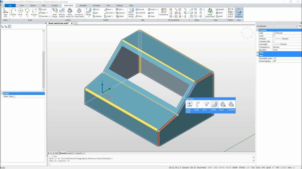
2. Getting Started with Sheet Metal
Setting Up BricsCAD for Sheet Metal
- Install BricsCAD: Ensure you have the latest version of BricsCAD installed on your computer.
- Enable Sheet Metal Workspace: Switch to the Sheet Metal workspace by selecting it from the workspace menu or using the
WORKSPACEcommand. - Set Up Preferences: Configure your sheet metal preferences, such as material properties, bend allowances, and default thickness, through the Sheet Metal Settings dialog.
Understanding Sheet Metal Terminology
- Bend: The curved portion of the sheet metal created by bending.
- Flange: A flat or angled extension from the edge of the sheet metal part.
- Tab: A small projection from the sheet metal used for joining or fastening.
- K-Factor: A value representing the neutral axis shift during bending.
- Bend Allowance: The amount of material added to the length of the flat pattern to account for bending.
3. Basic Sheet Metal Operations
Creating Sheet Metal Parts
- Create a Base Flange:
- Start with a sketch or a profile on a plane.
- Use the
SMFLANGEcommand to create a base flange from the sketch.
- Extrude the Base Flange:
- Define the thickness and direction of the extrusion to form the base sheet metal part.
Bending and Unbending Sheet Metal
- Bend:
- Use the
SMBENDcommand to create bends along specified edges or lines. - Define the bend radius and angle to achieve the desired shape.
- Use the
- Unbend:
- Use the
SMUNBENDcommand to flatten the bent sheet metal part. - This is useful for creating flat patterns and verifying dimensions.
- Use the
Adding Flanges and Tabs
- Add Flanges:
- Use the
SMFLANGEEDGEcommand to add flanges to the edges of the base flange. - Specify the flange height, angle, and bend radius.
- Use the
- Create Tabs:
- Use the
SMTABcommand to create tabs on the sheet metal part. - Define the tab size and position for fastening or joining purposes.
- Use the
4. Advanced Sheet Metal Techniques
Creating Complex Shapes
- Lofted Shapes:
- Use the
SMLOFTcommand to create lofted sheet metal parts between two or more profiles. - Define the profiles and guide curves to achieve complex shapes.
- Use the
- Hem and Jog:
- Use the
SMHEMandSMJOGcommands to create hems and jogs in the sheet metal part. - Specify the hem type, radius, and jog height.
- Use the
Using Lofted Sheet Metal
- Lofted Bend:
- Use the
SMLOFTEDBENDcommand to create lofted bends between two or more profiles. - Define the profiles and bend parameters to achieve smooth transitions.
- Use the
Adding Features like Holes and Cuts
- Create Holes:
- Use the
HOLEcommand to create holes in the sheet metal part. - Specify the hole size, shape, and position.
- Use the
- Add Cuts:
- Use the
CUTcommand to create cuts or slots in the sheet metal part. - Define the cut shape and position for precise modifications.
- Use the
5. Sheet Metal Tools and Commands
Sheet Metal Toolbar and Ribbon
- Toolbar:
- Access common sheet metal commands from the Sheet Metal toolbar.
- Customize the toolbar to include frequently used commands.
- Ribbon:
- Use the Sheet Metal ribbon tab to access a comprehensive set of sheet metal tools.
- Organize the ribbon to suit your workflow.
Essential Commands for Sheet Metal
- SMFLANGE: Create flanges from sketches or edges.
- SMBEND: Create bends along specified edges or lines.
- SMUNBEND: Flatten bent sheet metal parts.
- SMFLANGEEDGE: Add flanges to the edges of the base flange.
- SMTAB: Create tabs on the sheet metal part.
- SMLOFT: Create lofted sheet metal parts between profiles.
- SMHEM: Create hems in the sheet metal part.
- SMJOG: Create jogs in the sheet metal part.
- HOLE: Create holes in the sheet metal part.
- CUT: Create cuts or slots in the sheet metal part.
6. Managing Sheet Metal Parts
Editing and Modifying Sheet Metal Parts
- Direct Editing:
- Use direct editing tools to modify sheet metal parts.
- Adjust bends, flanges, and other features interactively.
- History-Based Editing:
- Use the design history to make changes to the sheet metal part.
- Modify parameters and features in the model tree.
Using Parametric Design
- Parametric Features:
- Define parametric features such as dimensions, constraints, and relations.
- Use the
PARAMcommand to create and manage parametric features.
- Parametric Modeling:
- Create parametric models that update automatically when parameters change.
- Use parametric design to achieve flexibility and precision.
Converting Solid Parts to Sheet Metal
- Solid to Sheet Metal:
- Use the
SMCONVERTcommand to convert solid parts to sheet metal parts. - Define the thickness, bends, and other sheet metal parameters.
- Use the
- Flattening Solids:
- Use the
SMFLATTENcommand to create flat patterns from solid parts. - Verify and adjust the flat pattern for manufacturing.
- Use the
7. Working with Assemblies
Creating and Managing Sheet Metal Assemblies
- Create Assemblies:
- Use the
ASSEMBLYcommand to create assemblies of sheet metal parts. - Add and position parts within the assembly.
- Use the
- Manage Assemblies:
- Use the Assembly Manager to organize and manage sheet metal assemblies.
- Define assembly constraints and mates.
Assembly Constraints and Mates
- Apply Constraints:
- Use the
CONSTRAINTcommand to apply geometric constraints between parts. - Define constraints such as parallel, perpendicular, and tangent.
- Use the
- Create Mates:
- Use the
MATEcommand to create mating relationships between parts. - Define mates such as coincident, distance, and angle.
- Use the
Exploded Views and Animations
- Create Exploded Views:
- Use the
EXPLODEcommand to create exploded views of assemblies. - Define the explosion direction and distance for each part.
- Use the
- Animate Exploded Views:
- Use the Animation Editor to create animations of exploded views.
- Define the sequence and timing of the animation.
8. Sheet Metal Documentation
Creating Drawings and Flat Patterns
- Generate Drawings:
- Use the
SMVIEWcommand to create drawing views of sheet metal parts. - Define the view type, scale, and position.
- Use the
- Create Flat Patterns:
- Use the
SMFLATTENcommand to create flat patterns for manufacturing. - Verify and adjust the flat pattern for accuracy.
- Use the
Annotating and Dimensioning Sheet Metal Parts
- Add Annotations:
- Use the
ANNOTATEcommand to add text, notes, and symbols to sheet metal drawings. - Define the annotation style and position.
- Use the
- Apply Dimensions:
- Use the
DIMcommand to apply dimensions to sheet metal parts. - Define the dimension type, style, and placement.
- Use the
Exporting to CNC and Other Formats
- Export Flat Patterns:
- Use the
EXPORTcommand to export flat patterns to CNC-compatible formats. - Define the export settings and file format (e.g., DXF, DWG).
- Use the
- Save As Other Formats:
- Use the
SAVEAScommand to save sheet metal parts and assemblies in various formats. - Define the file type and export settings.
- Use the
9. Best Practices for Sheet Metal Design
Design Guidelines and Tips
- Material Selection: Choose the appropriate material for your sheet metal design based on strength, flexibility, and cost.
- Bend Radius: Use the recommended bend radius for the material to avoid cracking or deformation.
- K-Factor: Calculate and use the correct K-factor for accurate bend allowances and flat patterns.
- Avoid Sharp Corners: Use fillets and rounds to avoid stress concentrations and cracking.
Avoiding Common Mistakes
- Incorrect Bend Allowances: Ensure correct bend allowances are used to avoid incorrect dimensions in flat patterns.
- Improper Material Thickness: Verify the material thickness to ensure it matches the design specifications.
- Inadequate Support: Provide adequate support and reinforcement for large or heavy sheet metal parts.
- Overlooking Manufacturing Constraints: Consider manufacturing constraints and capabilities when designing sheet metal parts.
Optimizing for Manufacturing
- Simplify Design: Simplify the design to reduce manufacturing complexity and costs.
- Minimize Waste: Optimize the layout and nesting of flat patterns to minimize material waste.
- Ensure Accuracy: Verify and adjust dimensions and tolerances for precise manufacturing.
- Collaboration: Collaborate with manufacturers to ensure the design meets their capabilities and requirements.
10. Troubleshooting and Support
Common Issues and Solutions
- Flat Pattern Errors: Verify and adjust the flat pattern to ensure it matches the 3D model and manufacturing requirements.
- Bend Distortions: Use the correct bend radius and allowances to avoid distortions and cracking.
- Incorrect Dimensions: Double-check dimensions and tolerances to ensure accuracy in the final product.
- Assembly Issues: Verify and adjust assembly constraints and mates for proper fit and function.
Resources for Learning More
- BricsCAD Documentation: Refer to the official BricsCAD documentation for detailed information and tutorials.
- Online Forums: Join online forums and communities to share knowledge and get help from other users.
- Training Courses: Enroll in training courses and workshops to improve your skills and knowledge.
Getting Help and Support
- Technical Support: Contact BricsCAD technical support for assistance with software issues and troubleshooting.
- User Guides: Refer to user guides and manuals for step-by-step instructions and best practices.
- Online Tutorials: Watch online tutorials and webinars for practical demonstrations and tips.
11. Conclusion
Working with sheet metal in BricsCAD provides a powerful and efficient solution for designing and manufacturing sheet metal parts and assemblies. By understanding the basic concepts, mastering advanced techniques, and following best practices, you can optimize your sheet metal design process and achieve superior results. Whether you are a beginner or an experienced user, the insights provided in this guide will help you harness the full potential of BricsCAD’s sheet metal capabilities for your projects.