Mastering Tool Deflection Simulation: A Comprehensive Guide
In the realm of precision machining, understanding and accounting for tool deflection is crucial for achieving optimal part quality, dimensional accuracy, and tool life. Tool deflection refers to the bending or deformation of a cutting tool under the forces exerted during machining operations, resulting in deviations from the intended toolpath and potentially compromising the integrity of the machined part. Simulating tool deflection allows manufacturers to predict and mitigate its effects, leading to improved machining performance and reduced scrap rates. In this comprehensive guide, we’ll delve into the intricacies of simulating tool deflection, exploring the importance, methods, challenges, and best practices associated with this critical aspect of machining simulation.
Understanding Tool Deflection
Before delving into tool deflection simulation, it’s essential to understand the factors that contribute to tool deflection and its impact on machining operations. Several factors influence tool deflection, including:
- Cutting Forces: The primary cause of tool deflection is the cutting forces generated during machining, which result from interactions between the cutting tool and the workpiece material.
- Tool Geometry: Factors such as tool geometry, including tool length, diameter, flute length, and cutting edge geometry, influence the susceptibility of a tool to deflection.
- Material Properties: Material properties of the workpiece material, such as hardness, strength, and ductility, affect the magnitude and direction of cutting forces and, consequently, tool deflection.
- Machining Parameters: Cutting parameters such as cutting speed, feed rate, depth of cut, and tool engagement play a significant role in determining the magnitude of cutting forces and, by extension, tool deflection.
Tool deflection can result in several undesirable consequences, including:
- Dimensional Inaccuracy: Tool deflection can cause deviations from the intended dimensions and tolerances of the machined part, leading to dimensional inaccuracies and potential rework.
- Poor Surface Finish: Excessive tool deflection can result in chatter marks, surface irregularities, or scalloped surfaces, compromising the surface finish of the machined part.
- Tool Wear and Breakage: Prolonged or severe tool deflection can accelerate tool wear and fatigue, leading to premature tool failure or breakage, necessitating tool replacement and downtime.
Importance of Tool Deflection Simulation
Given the significant impact of tool deflection on machining performance and part quality, simulating tool deflection is essential for several reasons:
- Predictive Analysis: Tool deflection simulation enables manufacturers to predict and visualize the deformation of cutting tools under various machining conditions, allowing for proactive mitigation strategies.
- Optimization of Cutting Parameters: By simulating tool deflection, manufacturers can identify optimal cutting parameters that minimize deflection while maximizing material removal rates and surface finish.
- Toolpath Optimization: Understanding tool deflection allows CAM programmers to optimize toolpaths to minimize deflection-induced deviations and improve machining accuracy.
- Tool Selection and Design: Tool deflection simulation aids in the selection and design of cutting tools with appropriate geometries, materials, and coatings to withstand the forces encountered during machining.
- Process Validation: Simulating tool deflection allows manufacturers to validate machining processes and tooling strategies before actual production runs, reducing the risk of costly errors and rework.
Methods for Simulating Tool Deflection
Simulating tool deflection can be accomplished using various methods, ranging from analytical models to finite element analysis (FEA) simulations:
- Analytical Models: Simplified analytical models, such as Euler-Bernoulli beam theory or Timoshenko beam theory, provide a theoretical framework for estimating tool deflection based on geometric and loading parameters. While less computationally intensive, analytical models may not capture the full complexity of tool-material interactions.
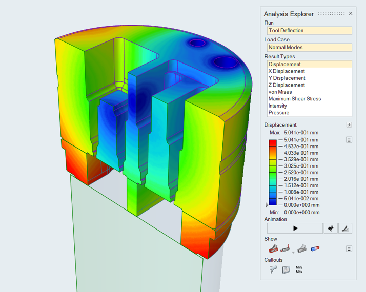
- Finite Element Analysis (FEA): FEA simulations offer a more detailed and accurate approach to simulating tool deflection by discretizing the cutting tool and workpiece geometry into finite elements and solving for the deformation behavior under applied loads. FEA software packages such as ANSYS, Abaqus, or COMSOL allow for comprehensive analysis of tool deflection under various machining conditions.
- Empirical Correlations: Empirical correlations derived from experimental data or manufacturer specifications can provide simplified relationships between cutting parameters, tool geometry, material properties, and tool deflection, offering a practical approach for estimating deflection in specific machining scenarios.
Challenges and Considerations
Simulating tool deflection poses several challenges and considerations that must be addressed to ensure accurate and reliable results:
- Material Modeling: Accurately modeling the material behavior of cutting tools and workpiece materials is essential for realistic simulation results. This requires precise characterization of material properties such as Young’s modulus, yield strength, and Poisson’s ratio.
- Contact Modeling: Proper modeling of the contact between the cutting tool and workpiece is critical for capturing the transfer of cutting forces and heat generation during machining accurately.
- Boundary Conditions: Applying realistic boundary conditions, including fixturing constraints and cutting tool mounting conditions, is crucial for simulating tool deflection in real-world machining environments.
- Solver Convergence: Achieving convergence in FEA simulations requires careful meshing, solver settings, and solution techniques to ensure accurate and stable results, especially for nonlinear materials and complex geometries.
- Validation and Calibration: Validating simulation results against experimental data and calibrating material models and boundary conditions are essential steps to ensure the accuracy and reliability of tool deflection simulations.
Best Practices for Tool Deflection Simulation
To maximize the effectiveness and reliability of tool deflection simulation, manufacturers should adhere to best practices:
- Model Validation: Validate simulation results against experimental data or benchmark cases to verify the accuracy and predictive capability of the simulation model.
- Sensitivity Analysis: Conduct sensitivity analyses to assess the influence of input parameters such as cutting speed, feed rate, and tool geometry on tool deflection and identify critical factors affecting machining performance.
- Mesh Refinement: Use fine meshing and adaptive mesh refinement techniques to capture localized deformations and stress concentrations accurately, especially in regions of high curvature or complex geometry.
- Concurrent Simulation: Integrate tool deflection simulation with other machining simulations, such as cutting forces, temperature distribution, and chip formation, to provide a comprehensive understanding of machining behavior and performance.
- Iterative Optimization: Implement iterative optimization algorithms to systematically explore the design space of cutting parameters and tool geometries and identify optimal solutions that minimize tool deflection while maximizing machining efficiency and quality.
Applications and Case Studies
Tool deflection simulation finds applications across various industries and machining processes:
- Milling Operations: Simulating tool deflection in milling operations helps optimize cutting parameters, toolpath strategies, and fixture designs to minimize deflection-induced errors and improve part accuracy and surface finish.
- Turning Operations: In turning operations, tool deflection simulation aids in tool selection, toolholder design, and process optimization to mitigate deflection-related issues such as taper, lobing, and surface roughness.
- Drilling and Hole Making: Simulating tool deflection in drilling and hole-making processes enables manufacturers to select appropriate drill geometries, cutting conditions, and coolant strategies to achieve precise hole dimensions and tolerances.
- Composite Machining: In composite machining, where delicate fibers and laminates are susceptible to damage from excessive forces, tool deflection simulation helps optimize toolpath strategies, tool designs, and cutting parameters to minimize delamination and fiber pullout.
Conclusion
In conclusion, simulating tool deflection is a critical aspect of machining simulation, enabling manufacturers to predict, understand, and mitigate the effects of tool deformation on part quality, dimensional accuracy, and tool life. By leveraging analytical models, finite element analysis (FEA), and empirical correlations, manufacturers can gain valuable insights into the complex interactions between cutting tools, workpiece materials, and machining conditions, leading to optimized processes, enhanced productivity, and improved machining performance. By adhering to best practices, addressing challenges, and applying tool deflection simulation across various machining operations, manufacturers can unlock new levels of precision, efficiency, and reliability in their manufacturing processes. Master the art of tool deflection simulation, and take your machining capabilities to the next level.