AutoCAD 3D Revolve Command Tutorial: Crafting Elegance in the Third Dimension
AutoCAD, the stalwart in computer-aided design (CAD), empowers designers to transcend the limits of 2D realms and venture into the immersive world of 3D modeling. Among the myriad tools at their disposal, the “Revolve” command emerges as a potent force, allowing users to sculpt intricate three-dimensional objects with grace and precision. In this extensive tutorial, we embark on a journey through the nuances of the AutoCAD 3D Revolve command, unveiling its functionalities, step-by-step procedures, and the transformative role it plays in elevating design to new heights of elegance and complexity.
I. Unveiling the AutoCAD 3D Revolve Command: A Symphony of Rotation and Form
A. What is the Revolve Command?
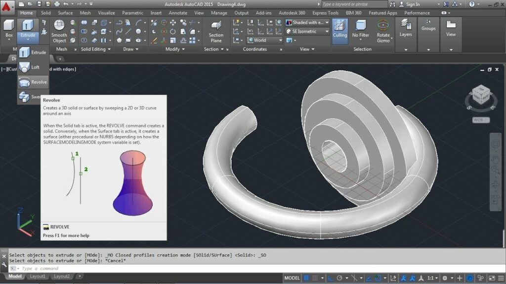
The Revolve command in AutoCAD is a dynamic tool that enables the creation of three-dimensional objects through rotation about an axis. It revolves 2D entities, typically closed shapes or profiles, around a specified axis to generate seamless, symmetrical, and intricate 3D solids. This command is particularly adept at crafting objects with rotational symmetry, from simple vases to complex engine components.
B. When to Use the Revolve Command
The Revolve command proves invaluable in scenarios where designers aim to:
- Create Rotational Symmetry: Craft objects that exhibit symmetry about a rotational axis, enhancing aesthetics and precision.
- Model Rotational Components: Design components of machinery, industrial equipment, or decorative elements that involve rotational symmetry.
- Generate Complex 3D Forms: Sculpt intricate shapes, such as lampshades, cups, or architectural details, that require the elegance of rotational design.
II. Accessing the AutoCAD 3D Revolve Command
A. Command Line Activation
To activate the Revolve command using the command line:
- Type “REVOLVE” or its abbreviated form “REV” in the command line.
- Press Enter to initiate the command.
B. Ribbon Panel Access
Alternatively, users can access the Revolve command through the ribbon panel:
- Navigate to the “3D Modeling” or “Solid Editing” tab on the ribbon.
- Locate the “Revolve” icon in the panel.
- Click on the icon to activate the command.
III. Step-by-Step Tutorial: How to Use the AutoCAD 3D Revolve Command
A. Creating a Simple Revolved Object
- Draw a 2D Profile:
- Begin by drawing a closed 2D shape or profile that represents one-half of the desired object.
- Ensure the profile is drawn on the plane perpendicular to the axis of revolution.
- Access the Revolve Command:
- Type “REVOLVE” in the command line or click on the “Revolve” icon in the ribbon panel.
- Select the Profile:
- Click on the closed profile to be revolved.
- Specify the Axis:
- Define the axis of revolution by selecting a line or specifying rotation parameters.
- Set the Angle of Revolution:
- Enter the angle or select two points to specify the extent of the revolution.
- Press Enter to confirm the creation of the revolved object.
- Review the 3D Solid:
- The 2D profile is seamlessly revolved around the specified axis, creating a symmetrical 3D solid.
B. Adjusting Revolve Parameters
- Modify the 2D Profile:
- Edit the original 2D profile by adjusting dimensions, adding details, or refining the shape.
- Update the Revolved Object:
- Repeat the Revolve command, selecting the modified profile and specifying the axis.
- The 3D object updates dynamically, reflecting changes made to the original profile.
C. Revolving with Reference Axes
- Draw a Reference Axis:
- Create a line or construction axis to serve as the rotational axis for the revolved object.
- Access the Revolve Command:
- Activate the Revolve command and select the closed profile to be revolved.
- Specify the Reference Axis:
- Choose the reference axis to define the rotation axis for the revolved object.
- Confirm the revolve parameters to complete the process.
- Review the Result:
- The 2D profile is revolved around the specified reference axis, creating a tailored 3D object.
IV. Advanced Techniques with AutoCAD 3D Revolve Command
A. Multiple Revolutions
The Revolve command supports multiple revolutions for creating helical or spiral forms. Users can specify the angle of revolution or dynamically adjust it during the command, allowing for the creation of intricate spiraled objects.
B. Combining Revolve with Other Commands
Integrate the Revolve command with other 3D modeling tools in AutoCAD to enhance versatility. Combine revolved objects with Union, Subtract, or Intersect commands to create complex assemblies or refine existing models.
C. Hollow Revolved Objects
To create hollow objects, draw a concentric inner profile within the original closed profile. Use the Revolve command on both profiles, creating an outer shell and an inner void. Combine the two revolved objects to form a hollow structure.
V. Troubleshooting and Considerations
A. Closed and Continuous Profiles
Ensure that the 2D profile selected for revolving is closed and continuous. Gaps or open sections in the profile may result in unexpected outcomes.
B. Axis Placement and Alignment
Carefully select and position the axis of revolution. Misalignment or incorrect placement of the axis can lead to asymmetrical or undesired results.
C. Managing Complex Profiles
For intricate designs with multiple details, consider breaking down the profile into simpler closed shapes. Revolve each segment individually and combine the revolved objects to form the complete 3D model.
VI. Future Trends and Advancements in AutoCAD 3D Modeling
As AutoCAD continues to evolve, the Revolve command is poised to witness enhancements and additional features. Expect improvements in real-time feedback, user interfaces, and seamless integration with emerging technologies like augmented reality (AR) and virtual reality (VR) for more immersive design experiences.
VII. Conclusion: Revolve Command – A Dance of Form and Precision
The AutoCAD 3D Revolve command stands as a testament to the software’s commitment to providing designers with an intuitive and powerful tool for creating elegant, symmetrical, and intricate 3D forms. By harnessing the rotational power of the Revolve command, designers can sculpt objects that transcend the boundaries of traditional design, adding a touch of grace and sophistication to their projects.
This tutorial provides a solid foundation for users to master the Revolve command, unlocking the potential to create captivating 3D models that captivate the eye and spark the imagination. Armed with the knowledge imparted in this tutorial, designers can infuse their creations with rotational symmetry, breathing life into everything from industrial components to artistic masterpieces.
In the ever-evolving realm of digital design, the Revolve command in AutoCAD remains a virtuoso, orchestrating a dance of form and precision that transforms static 2D entities into dynamic and visually stunning 3D objects. As designers continue to push the boundaries of what is possible, the Revolve command stands ready to be a guiding force, facilitating the creation of works that embody the essence of elegance and complexity in the third dimension.