Mastering Swept Features in SolidWorks: A Comprehensive Guide
Introduction: SolidWorks, a leading computer-aided design (CAD) software, empowers engineers and designers to translate their creative visions into tangible 3D models. Among its diverse array of features, swept features stand out as powerful tools for creating complex shapes by sweeping a 2D sketch along a defined path. In this extensive guide, we’ll explore the intricacies of creating swept features in SolidWorks, covering fundamental concepts, essential techniques, and advanced strategies to help you harness the full potential of this versatile tool.
Understanding Swept Features: Swept features in SolidWorks involve moving a 2D sketch profile along a specified path to generate a three-dimensional solid or surface geometry. This method enables the creation of a wide range of shapes, from simple extrusions to intricate profiles with variable cross-sections. Before diving into the specifics of swept features, it’s crucial to grasp some foundational concepts:
- Sketching:
- Sketching serves as the foundation of design in SolidWorks, allowing users to create 2D profiles using a variety of sketch entities such as lines, arcs, circles, and splines.
- Paths:
- Paths define the trajectory along which the sketch profile is swept to create the desired feature. Paths can be straight, curved, or complex, providing flexibility in defining the shape of the swept feature.
- Swept Feature:
- The Swept Feature command in SolidWorks enables users to sweep a sketch profile along a defined path to create a solid or surface feature. Users can control parameters such as orientation, scaling, and twist to customize the swept geometry.
Creating Swept Features in SolidWorks: SolidWorks offers a comprehensive set of tools and options for creating swept features efficiently and accurately. Let’s explore the essential tools and techniques for generating swept geometry:
- Swept Boss/Base:
- The Swept Boss/Base command is the primary tool for creating swept features in SolidWorks. Users begin by selecting a sketch profile and a path, and SolidWorks sweeps the profile along the path to generate the feature.
- Swept Cut:
- Similar to Swept Boss/Base, the Swept Cut command allows users to create cutouts or voids by sweeping a sketch profile along a path. This tool is useful for creating channels, grooves, and other features within a part.
- Path Selection:
- SolidWorks provides various methods for defining the sweep path, including selecting existing model edges, sketch lines, or reference geometry. Users can also create custom paths using sketch entities or curves.
Advanced Sweeping Techniques: In addition to basic sweep tools, SolidWorks offers advanced techniques to enhance the sweep feature creation process and achieve complex geometries:
- Variable Section Sweep:
- The Variable Section Sweep feature enables users to create swept features with varying cross-sectional profiles along the length of the sweep. This tool is ideal for generating tapered or non-uniform shapes.
- Guide Curves:
- Guide curves allow users to control the shape of swept features by defining additional curves or paths for the sweep operation to follow. This technique provides greater flexibility and creativity in design.
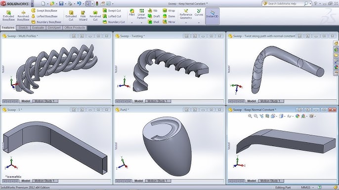
- Twist Along Path:
- SolidWorks allows users to apply a twist along the sweep path, enabling the creation of helical or spiraled features. This feature adds complexity and visual interest to swept geometry.
Best Practices for Swept Features: To maximize efficiency and maintain design integrity when creating swept features in SolidWorks, it’s essential to adhere to best practices:
- Sketch Preparation:
- Before creating a swept feature, ensure that the sketch profile is fully defined, error-free, and positioned correctly relative to the sweep path. Use sketch constraints and dimensions to control the shape and size of the profile.
- Path Selection:
- Carefully select or create the sweep path to ensure that it accurately represents the desired trajectory for the swept feature. Consider using reference geometry or model edges for precise path definition.
- Symmetry and Design Intent:
- Leverage symmetry and design intent to streamline the creation of swept features and maintain consistency throughout the design. Design with future modifications in mind, ensuring that the swept feature adapts gracefully to changes in design requirements.
- Test and Iterate:
- Regularly test and iterate on swept features to evaluate their functionality and performance. Use tools like interference detection and simulation to identify potential issues and optimize the design accordingly.
Conclusion: Swept features are invaluable tools in SolidWorks, offering a flexible and efficient method for creating complex geometries with ease. By mastering the tools and techniques for creating swept features, engineers and designers can unlock new realms of creativity and efficiency in their design workflows. Whether you’re a novice or an experienced SolidWorks user, understanding the principles of swept features and applying best practices will elevate your design capabilities and enable you to bring your concepts to life with precision and elegance.