Unleashing Design Potential: A Comprehensive Guide to Creating Revolved Features in SolidWorks
Introduction: SolidWorks stands as a pinnacle of computer-aided design (CAD), providing engineers and designers with a powerful toolset to bring their concepts to life in three dimensions. Among the multitude of features SolidWorks offers, revolved features stand out as a versatile method for generating complex 3D geometries from 2D sketches. In this comprehensive guide, we’ll embark on a journey through the intricacies of creating revolved features in SolidWorks, from the basics to advanced techniques that unlock the full potential of this transformative tool.
Understanding Revolved Features: Revolved features in SolidWorks are created by rotating a 2D sketch profile about an axis to generate a solid or surface geometry. This rotational symmetry enables the creation of cylindrical, conical, and even organic shapes with ease. Before diving into the specifics of revolved features, it’s essential to grasp some foundational concepts:
- Sketching:
- Sketching serves as the foundation of design in SolidWorks, allowing users to create 2D profiles using a variety of sketch entities such as lines, arcs, circles, and splines.
- Axes:
- Axes are imaginary lines around which revolved features are created. They define the axis of rotation and serve as a reference for generating symmetrical geometry.
- Revolve Feature:
- The Revolve feature in SolidWorks enables users to rotate a sketch profile about an axis to create a solid or surface feature. Users can control parameters such as angle, direction, and end conditions to customize the revolved geometry.
Creating Revolved Features in SolidWorks: SolidWorks provides a plethora of tools and options for creating revolved features efficiently and accurately. Let’s explore some of the essential tools and techniques for generating revolved geometry:
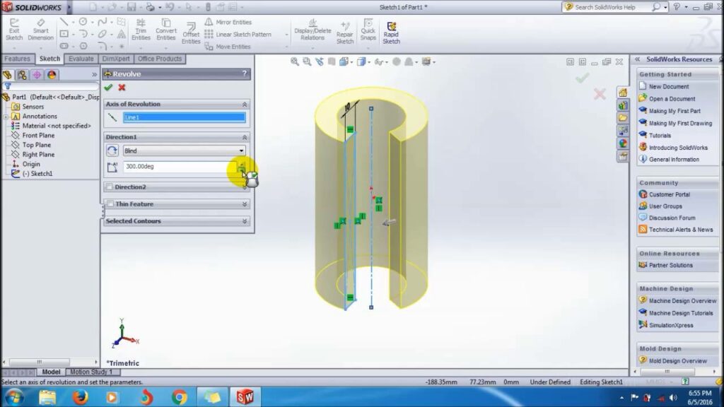
- Revolve Boss/Base:
- The Revolve Boss/Base command is the primary tool for creating revolved features in SolidWorks. Users begin by selecting a sketch profile and defining an axis of rotation. The software then generates the revolved feature based on user-defined parameters.
- Revolve Cut:
- Similar to Revolve Boss/Base, the Revolve Cut command allows users to create cutouts or cavities by revolving a sketch profile about an axis. This tool is useful for creating holes, pockets, and other features within a part.
- Axis of Revolution:
- SolidWorks provides multiple methods for defining the axis of revolution, including selecting existing model edges, sketch lines, or reference geometry. Users can also create custom axes using the Axis feature.
Advanced Revolving Techniques: In addition to basic revolve tools, SolidWorks offers several advanced techniques to enhance the revolve feature creation process and achieve complex geometries:
- Variable Section Swept:
- The Variable Section Swept feature enables users to create revolved features with varying cross-sectional profiles along the length of the revolve. This tool is particularly useful for generating tapered or non-uniform shapes.
- Guide Curves:
- Guide curves allow users to control the shape of revolved features by defining additional curves or paths for the revolve operation to follow. This technique provides greater flexibility and creativity in design.
- Surface Revolve:
- SolidWorks also supports the creation of revolved surface features, which generate surface geometry instead of solid bodies. Surface revolve features are useful for creating complex organic shapes or lofted surfaces.
Best Practices for Revolved Features: To maximize efficiency and maintain design integrity when creating revolved features in SolidWorks, it’s essential to follow these best practices:
- Sketch Preparation:
- Before creating a revolved feature, ensure that the sketch profile is fully defined, free of errors, and positioned correctly relative to the axis of revolution. Use sketch constraints and dimensions to control the shape and size of the profile.
- Axis Selection:
- Carefully select or create the axis of revolution to ensure that it accurately represents the desired rotational axis for the revolved feature. Consider using reference geometry or model edges for precise axis definition.
- Symmetry and Design Intent:
- Leverage the symmetry inherent in revolved features to streamline design and maintain consistency. Design with future modifications in mind, ensuring that the revolved feature adapts gracefully to changes in design requirements.
- Test and Iterate:
- Regularly test and iterate on revolved features to evaluate their functionality and performance. Use tools like interference detection and simulation to identify potential issues and optimize the design accordingly.
Conclusion: Revolved features stand as a cornerstone of design in SolidWorks, offering a powerful method for creating symmetrical and complex 3D geometries from 2D sketches. By mastering the tools and techniques for creating revolved features, engineers and designers can unlock new realms of creativity and efficiency in their design workflows. Whether you’re a novice or an experienced SolidWorks user, understanding the principles of revolved features and applying best practices will elevate your design capabilities and enable you to bring your concepts to life with precision and elegance.