Mastering Sketch Extrusion in SolidWorks: A Comprehensive Guide
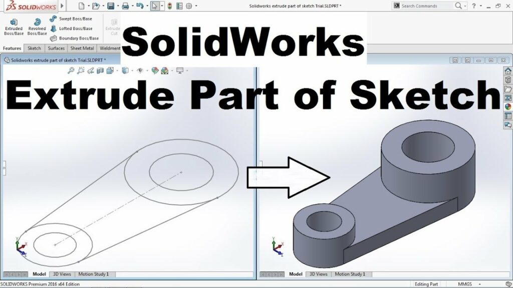
Introduction: SolidWorks, a leading computer-aided design (CAD) software, empowers engineers and designers to bring their ideas to life in three dimensions. One of the fundamental operations in SolidWorks is sketch extrusion, a process that transforms 2D sketches into 3D models by adding depth. In this comprehensive guide, we’ll delve into the intricacies of sketch extrusion in SolidWorks, covering everything from basic techniques to advanced tips for optimizing your designs.
Understanding Sketch Extrusion Basics: Sketch extrusion is the process of extending a 2D sketch along a specified direction to create a 3D solid or surface model. Before diving into the specifics of sketch extrusion, it’s crucial to grasp some foundational concepts:
- Sketching:
- Sketching is the primary method of creating geometry in SolidWorks. It involves drawing 2D shapes and profiles using sketch entities such as lines, arcs, circles, and rectangles.
- Sketch Planes:
- Sketches are created on predefined planes within the SolidWorks environment, such as the front, top, or right planes. These planes serve as reference surfaces for sketching and extrusion operations.
- Extrude Feature:
- The Extrude feature in SolidWorks allows users to convert 2D sketches into 3D geometry by adding thickness or depth. Extrusion can be performed in various directions, including linear, symmetric, and mid-plane.
Sketch Extrusion Tools in SolidWorks: SolidWorks provides a range of tools and options for performing sketch extrusion efficiently and accurately. Let’s explore some of the essential extrusion tools available:
- Extrude Boss/Base:
- The Extrude Boss/Base command is used to extrude sketch profiles outward to create solid features. Users can specify the extrusion distance, direction, and end condition (e.g., blind, through all, up to next).
- Extrude Cut:
- The Extrude Cut command is similar to Extrude Boss/Base but removes material instead of adding it. It enables users to create cutouts, holes, and cut-through features within a model.
- Thin Feature:
- The Thin Feature command allows users to extrude thin-walled sections of a sketch, such as sheet metal components. It provides options for defining thickness, material, and bend allowance.
Advanced Extrusion Techniques: In addition to basic extrusion tools, SolidWorks offers several advanced techniques to enhance the extrusion process and optimize design workflows:
- Draft:
- Draft is a feature that applies a taper or angle to the walls of an extruded feature. It is commonly used in manufacturing to facilitate mold release and improve part functionality.
- Shell:
- The Shell feature removes material from the interior of a solid model to create a hollow cavity. It is useful for lightweighting parts, reducing material costs, and accommodating internal components.
- Variable Thickness:
- SolidWorks allows users to create variable thickness extrusions by defining different thickness values along the length of the extruded feature. This feature is particularly useful for creating tapered or contoured shapes.
Best Practices for Sketch Extrusion: To achieve optimal results and maintain design integrity, it’s essential to adhere to best practices when performing sketch extrusion in SolidWorks:
- Plan Ahead:
- Before extruding a sketch, carefully plan the design and consider factors such as material properties, manufacturing constraints, and assembly requirements.
- Sketch Cleanup:
- Ensure that sketches are fully defined and free of errors before extruding them. Use tools like Trim, Extend, and Fillet to clean up sketch geometry and remove unwanted elements.
- Use Reference Geometry:
- Leverage reference geometry tools such as planes, axes, and points to aid in sketch creation and extrusion alignment. This ensures accuracy and consistency throughout the design process.
- Test and Iterate:
- Regularly test and iterate on extruded features to evaluate their functionality and performance. Use simulation tools to analyze stress, deflection, and other factors that may impact part behavior.
Conclusion: Sketch extrusion is a fundamental operation in SolidWorks that allows designers and engineers to transform 2D sketches into 3D models with depth and dimension. By mastering extrusion techniques and leveraging advanced features, users can create complex geometries, optimize part designs, and streamline the manufacturing process. Whether you’re a novice or an experienced SolidWorks user, understanding the principles of sketch extrusion and applying best practices will elevate your design capabilities and unlock new possibilities in CAD innovation.