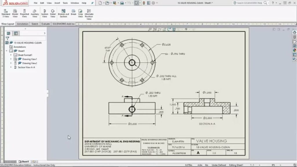
Mastering Dimensioning in SolidWorks: A Comprehensive Guide

Introduction: SolidWorks is a powerful computer-aided design (CAD) software used by engineers, designers, and manufacturers worldwide to create precise 3D models. Dimensioning in SolidWorks is a crucial aspect of the design process, as it allows users to define the size, shape, and position of features within a model accurately. In this comprehensive guide, we’ll explore everything you need to know about dimensioning in SolidWorks, from basic techniques to advanced tips for efficient and precise dimensioning.
Understanding Dimensioning Basics: Dimensioning in SolidWorks involves adding numerical values to sketches and features to specify their size and location. Before diving into the specifics of dimensioning, it’s essential to understand some basic concepts:
- Sketch Entities:
- Sketch entities are the basic building blocks of SolidWorks models, such as lines, circles, rectangles, and arcs. These entities are used to create 2D sketches that form the foundation of 3D models.
- Dimensions:
- Dimensions are numerical values that define the size, shape, and position of sketch entities and features within a SolidWorks model. They include linear dimensions (length, width, height), angular dimensions (angles), and radial dimensions (curved features).
- Constraints:
- Constraints are geometric relationships applied to sketch entities to control their behavior and maintain design intent. Examples include horizontal/vertical alignment, parallelism, perpendicularity, and symmetry.
Dimensioning Tools in SolidWorks: SolidWorks provides a variety of dimensioning tools to accurately define sketch geometry and features. Let’s explore some of the essential dimensioning tools available:
- Smart Dimension:
- The Smart Dimension tool allows users to add dimensions directly to sketch entities by clicking on the desired geometry and specifying the dimension value. SolidWorks automatically applies appropriate constraints to maintain sketch integrity.
- Dimension Tool:
- The Dimension tool enables users to add dimensions manually by selecting sketch entities and specifying dimension values through input fields. This tool offers more control over dimension placement and orientation.
- Fully Define Sketch:
- The Fully Define Sketch tool analyzes sketch geometry and automatically adds dimensions and constraints to fully define the sketch. This ensures that all sketch entities are constrained properly, reducing the likelihood of errors.
Advanced Dimensioning Techniques: In addition to basic dimensioning tools, SolidWorks offers several advanced techniques to streamline the dimensioning process and improve design efficiency:
- Ordinate Dimensions:
- Ordinate dimensions allow users to reference a common origin point (datum) and specify the distance of sketch entities along horizontal or vertical axes. This method simplifies dimensioning for complex sketches and ensures consistent alignment.
- Baseline and Chain Dimensions:
- Baseline and chain dimensions are used to dimension multiple features or sketch entities relative to a common baseline or chain. This approach is particularly useful for dimensioning patterns, arrays, and repetitive geometry.
- Dimension Equations:
- Dimension equations enable users to define dimensions based on mathematical expressions or relationships. This powerful feature allows for parametric design, where dimensions are driven by variables and formulas, facilitating design automation and optimization.
Best Practices for Dimensioning: To ensure clarity, accuracy, and consistency in dimensioning, it’s essential to follow these best practices:
- Maintain Design Intent:
- Always dimension sketches and features in a way that reflects the intended design requirements and specifications. Consider how changes to dimensions may impact the overall design and functionality.
- Use Logical Dimensioning:
- Arrange dimensions in a clear and organized manner to avoid clutter and confusion. Group related dimensions together and use appropriate spacing and alignment for readability.
- Avoid Over-Dimensioning:
- Only add dimensions that are necessary to define the geometry and features of the model. Avoid redundant or excessive dimensions that can clutter the drawing and make it difficult to interpret.
- Review and Validate Dimensions:
- Regularly review dimensioned sketches and features to ensure accuracy and consistency. Use tools like the Dimension Expert and Check Sketch for errors and inconsistencies.
Conclusion: Dimensioning is a critical aspect of the design process in SolidWorks, enabling users to communicate design intent accurately and efficiently. By mastering dimensioning techniques and following best practices, designers and engineers can create precise 3D models that meet design requirements and specifications. Whether you’re a beginner or an experienced SolidWorks user, understanding dimensioning fundamentals and utilizing advanced dimensioning tools will enhance your design workflow and ultimately lead to better design outcomes.


