Navigating Design with Precision: An In-Depth Exploration of AutoCAD Polar Coordinates
Introduction:
In the vast landscape of Computer-Aided Design (CAD), precision is the key to transforming ideas into tangible drawings. AutoCAD, a pioneering software in the CAD domain, provides a myriad of tools to enhance accuracy and efficiency in the drafting process. Among these tools, polar coordinates stand out as a fundamental feature, allowing users to define points, distances, and angles with unparalleled precision. This comprehensive guide aims to unravel the intricacies of AutoCAD polar coordinates, providing a detailed exploration of their functionalities, applications, and impact on the art of design.
Section 1: Unveiling AutoCAD Polar Coordinates
1.1 Defining Polar Coordinates: AutoCAD polar coordinates represent a system where the position of a point is defined by a distance and an angle relative to a reference point. Unlike rectangular or Cartesian coordinates, polar coordinates simplify the input process by relying on distance and angular measures, making them especially useful for tasks involving circular or radial designs.
1.2 Polar vs. Cartesian Coordinates: Dive into the comparative analysis of polar and Cartesian coordinates within the AutoCAD environment. Understand the advantages and applications of polar coordinates, especially when dealing with circular layouts, radial patterns, or projects that demand precision in angular relationships.
Section 2: Syntax and Usage of Polar Coordinates
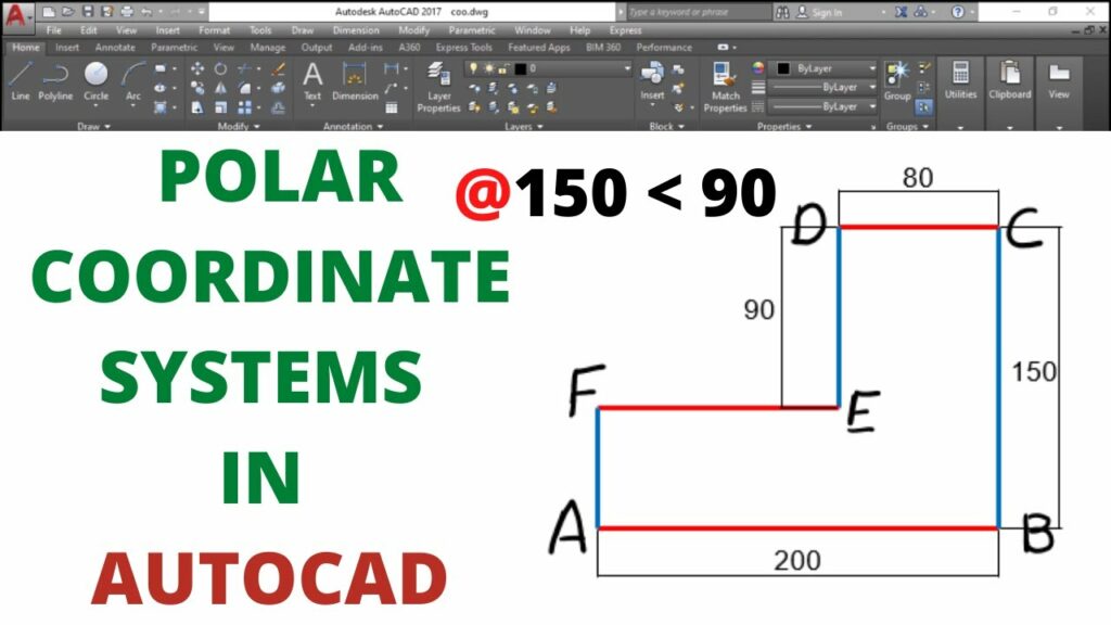
2.1 Polar Coordinate Syntax: Explore the syntax used to input polar coordinates in AutoCAD. Familiarize yourself with the @ symbol, distance, angle, and the importance of the < symbol when specifying angles.
2.2 Angle Formats: Delve into the different angle formats available in AutoCAD, such as degrees, minutes, seconds (DMS) or decimal degrees. Understand how to seamlessly switch between these formats based on project requirements.
Section 3: Basic Operations Using Polar Coordinates
3.1 Creating Objects: Discover how polar coordinates streamline the process of creating objects in AutoCAD. Learn to draw lines, circles, and polygons with precision using distance and angular measurements.
3.2 Editing Objects: Explore how polar coordinates enhance the editing of existing objects. From rotating and copying to scaling and stretching, understand how polar coordinates provide accuracy in modifying design elements.
Section 4: Dynamic Input and Polar Coordinates
4.1 Dynamic Input Features: Understand how AutoCAD’s dynamic input feature complements the use of polar coordinates. Learn how real-time feedback and input options enhance the precision and speed of drafting tasks.
4.2 Configuring Dynamic Input for Polar Coordinates: Navigate through the settings to configure dynamic input for optimal use with polar coordinates. Explore customization options to tailor the dynamic input to individual preferences and project requirements.
Section 5: Advanced Techniques and Tips
5.1 Array and Polar Array Commands: Discover advanced techniques using AutoCAD’s Array and Polar Array commands in conjunction with polar coordinates. Explore how these tools can expedite the creation of repetitive design elements.
5.2 Parametric Design with Polar Coordinates: Understand how polar coordinates facilitate parametric design in AutoCAD. Explore the concept of parametric constraints and how they interact with polar coordinates to create dynamic and adaptive designs.
Section 6: Polar Coordinates in 3D Modeling
6.1 Adapting Polar Coordinates to 3D: Explore the application of polar coordinates in the three-dimensional drafting environment of AutoCAD. Learn how to extend the use of polar coordinates beyond 2D designs for precision in 3D modeling.
6.2 Aligning Objects in 3D Space: Understand how polar coordinates aid in aligning objects in 3D space. Explore techniques for specifying distances and angles for elevated levels of accuracy in three-dimensional designs.
Section 7: Challenges and Troubleshooting
7.1 Common Mistakes with Polar Coordinates: Address common pitfalls and mistakes associated with using polar coordinates in AutoCAD. Learn how to identify and rectify errors to maintain precision in your drawings.
7.2 Troubleshooting Tips: Explore troubleshooting tips for resolving issues related to polar coordinates. From unexpected results to coordinate system shifts, gain insights into effective problem-solving strategies.
Conclusion:
As we conclude this exhaustive exploration of AutoCAD polar coordinates, it is evident that this feature is an indispensable tool for achieving precision and efficiency in CAD design. Whether you are a novice seeking to enhance your drafting skills or a seasoned professional navigating complex projects, mastering polar coordinates unlocks a realm of possibilities. Embrace the accuracy, simplicity, and versatility that polar coordinates bring to your AutoCAD workflow, and witness how this fundamental feature transforms your designs from concepts to meticulously crafted drawings. With continuous practice and application, you will navigate the intricate landscape of drafting with confidence, producing drawings that stand as testaments to the power of precision in AutoCAD.