Unleashing Design Versatility: A Comprehensive Guide to Creating Lofted Features in SolidWorks
Introduction: SolidWorks, a leading computer-aided design (CAD) software, empowers engineers and designers to transform their ideas into tangible 3D models with precision and efficiency. Among its diverse array of features, lofted features stand out as powerful tools for generating complex and organic shapes by blending multiple cross-section profiles along a defined path. In this extensive guide, we’ll delve into the intricacies of creating lofted features in SolidWorks, covering fundamental concepts, essential techniques, and advanced strategies to help you harness the full potential of this versatile tool.
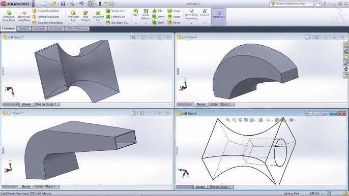
Understanding Lofted Features: Lofted features in SolidWorks involve creating a smooth transition between two or more cross-sectional profiles by interpolating intermediate shapes along a specified path. This method enables the creation of complex geometries with varying shapes and dimensions, making it ideal for creating aerodynamic forms, ergonomic designs, and intricate surfaces. Before exploring the specifics of lofted features, it’s crucial to grasp some foundational concepts:
- Sketching:
- Sketching serves as the building block of design in SolidWorks, allowing users to create 2D profiles using a variety of sketch entities such as lines, arcs, circles, and splines.
- Guide Curves:
- Guide curves define the path along which the lofted feature is generated. These curves can be straight, curved, or complex, providing flexibility in defining the shape and trajectory of the loft.
- Lofted Feature:
- The Lofted Feature command in SolidWorks enables users to create a smooth transition between two or more cross-sectional profiles by interpolating intermediate shapes along a defined path. Users can control parameters such as orientation, scaling, and guide curve influence to customize the lofted geometry.
Creating Lofted Features in SolidWorks: SolidWorks offers a comprehensive set of tools and options for creating lofted features efficiently and accurately. Let’s explore the essential tools and techniques for generating lofted geometry:
- Lofted Boss/Base:
- The Lofted Boss/Base command is the primary tool for creating lofted features in SolidWorks. Users begin by selecting two or more cross-sectional profiles and defining guide curves to control the loft’s trajectory. SolidWorks then generates the lofted feature based on user-defined parameters such as orientation, scaling, and guide curve influence.
- Lofted Cut:
- Similar to Lofted Boss/Base, the Lofted Cut command allows users to create cutouts or voids by lofting two or more cross-sectional profiles along a defined path. This tool is useful for creating complex cutouts, grooves, and other features within a part.
- Guide Curve Selection:
- SolidWorks provides various methods for defining guide curves, including selecting existing model edges, sketch lines, or reference geometry. Users can also create custom guide curves using sketch entities or curves.
Advanced Lofting Techniques: In addition to basic lofting tools, SolidWorks offers advanced techniques to enhance the loft feature creation process and achieve complex geometries:
- Variable Section Loft:
- The Variable Section Loft feature enables users to create lofted features with varying cross-sectional profiles along the loft trajectory. This tool is ideal for generating tapered or non-uniform shapes.
- Guide Curve Influence:
- Guide curve influence allows users to control the shape and trajectory of the lofted feature by adjusting the influence of guide curves. This technique provides greater flexibility and creativity in design.
- Tangency Control:
- SolidWorks allows users to control the tangency between adjacent loft sections, ensuring smooth transitions and curvature continuity. This feature is essential for achieving high-quality surface finishes and aesthetic designs.
Best Practices for Lofted Features: To maximize efficiency and maintain design integrity when creating lofted features in SolidWorks, it’s essential to adhere to best practices:
- Profile Preparation:
- Before creating a lofted feature, ensure that the cross-sectional profiles are fully defined, error-free, and positioned correctly relative to the loft path. Use sketch constraints and dimensions to control the shape and size of the profiles.
- Guide Curve Selection:
- Carefully select or create guide curves to ensure that they accurately represent the desired trajectory for the lofted feature. Consider using reference geometry or model edges for precise guide curve definition.
- Symmetry and Design Intent:
- Leverage symmetry and design intent to streamline the creation of lofted features and maintain consistency throughout the design. Design with future modifications in mind, ensuring that the lofted feature adapts gracefully to changes in design requirements.
- Test and Iterate:
- Regularly test and iterate on lofted features to evaluate their functionality and performance. Use tools like curvature analysis and surface deviation analysis to identify potential issues and optimize the design accordingly.
Conclusion: Lofted features are indispensable tools in SolidWorks, offering a flexible and efficient method for creating complex and organic geometries with ease. By mastering the tools and techniques for creating lofted features, engineers and designers can unlock new realms of creativity and efficiency in their design workflows. Whether you’re a novice or an experienced SolidWorks user, understanding the principles of lofted features and applying best practices will elevate your design capabilities and enable you to bring your concepts to life with precision and elegance.